
I’m using my blog as a place to store information about this project. 99 percent of it will be only of interest to me. I considered making it private, but if someone wants to follow along, here’s what I’m doing:
TowBot Project
Brains: This is where I’ll paste all the development stuff for the navigation control.
Useful blogs and links:
T-Beam
https://github.com/LilyGO/TTGO-T-Beam Original T-beam GitHub no moved to:
https://github.com/Xinyuan-LilyGO/LilyGO-T-Beam
https://platformio.org/lib/show/6657/AXP202X_Library Peripheral and power control module used on T-beam later versions
Design ESP32 LoRa GPS Tracker Applications with TTGO T-Beam Board
Some useful info on V.7 t-beam
https://www.dellascolto.com/bitwise/2020/07/31/ttgo-t-beam/ Very useful into on T-Beam with code for tracker using TTN—the things network. The code looks very useful.
https://www.hackster.io/news/the-ttgo-t-beam-an-esp32-lora-board-d44b08f18628 Article ion T-beam, might be useful
https://github.com/LilyGO/TTGO-T-Beam/issues/3 Fix fot V.7 power glitch issues. I probably should just ditch these V.7 boards. I’m certainly not going to use them for the TowBot.
https://rntlab.com/question/cant-compile-code-examples-for-ttgo-lora32-sx1276-oled-board/ My thread on board probs with macOS
LoRa
https://www.instructables.com/ESP32-Long-Distance-LoRaWan/ Very good article on LoRa. Code comments are in Portuguese.
https://randomnerdtutorials.com/ttgo-lora32-sx1276-arduino-ide/ Excellent LoRa stuff and well-explained code. Super useful
https://www.thethingsnetwork.org/community/berlin/post/warning-attention-users-of-ttgo21-v16-boards-labeled-t3_v16-on-pcb-battery-exploded-and-got-on-fire Battery charge problem with TTGO LoRa boards
https://makeradvisor.com/esp32-sx1276-lora-ssd1306-oled/ RNT (Maker Advisor) info on best LoRa boards
T-Display
https://www.reddit.com/r/arduino/comments/cgpwad/anyone_got_the_ttgotdisplay_esp32_board_working/ Reddit Arduino forum tells how to get ESP32 working after macOS change and useful info on TTGO T-display
https://oneguyoneblog.com/2020/09/28/lilygo-ttgo-t-display-esp32-with-tft-lcd/ Good T-display article
https://github.com/Xinyuan-LilyGO/TTGO-T-Display T-Display GitHub
AXP2xxx
https://platformio.org/lib/show/6657/AXP202X_Library AXP info and code examples
http://www.x-powers.com/en.php/Info/product_detail/article_id/30 AXP product info
And now on with the show
Most of the information posted online refers to the board setup in the Arduino IDE as Tools>Boards>ESP32 Dev Module with some specific parameters changed but with the latest ESP32 board JSON there is a T-Beam selection which seems to work well. I did a post on my blog that references this and some issues with ESP32 boards running the Arduino IDE on macOS. I’m pasting the relevant section here:
Imagine my surprise when I discovered that code I’d written that runs on ESP32 boards would no longer compile–even simple little projects like my lighting control system for Fritz, the motorhome. I don’t generally use my Mac for developing Arduino stuff, but I have used it before and all the projects I’ve developed have lived at various times on both platforms. It turns out that the Big Sur release of the macOS breaks some of the Python stuff in the guts of the Arduino IDE, specifically in how it interacts with the ESP boards. Figuring out a workaround took quite a bit of digging. I finally found a solution on Github that uses what I assume is a beta release of the board extension for ESP32. This is the GitHub topic, I’d post the URL but that’s just Github.com:
MacOS Big Sur dlsym(RTLD_DEFAULT, kIOMasterPortDefault): symbol not found (ESPTOOL-82) #540
And if you’re trying to fix a similar problem here’s the address for a beta version board manager JSON script that you paste into Preferences>additional board manager URLs instead of the stable release URL (which results in an installation that doesn’t work): https://raw.githubusercontent.com/espressif/arduino-esp32/gh-pages/package_esp32_dev_index.json
This is all a longwinded way to say that in the process of digging and fiddling I found three ESP32 boards that are my new favorites, all from LilyGo. The first is the LilyGO TTGO T-Display. It’s about as cheap an ESP32 board as I’ve found, and it includes a 240×135 pixel IPS TFT display, 4MB SPIFF, WiFi, Bluetooth, built-in antenna, CP2104 USB-to-UART (that’s a good thing–supports higher transfer rates), and a 3.7V battery charging circuit. The battery management is a bit spooky as it seems to supply 5V to the 3.7V LiPo when the USB adapter is connected. I didn’t test this with a battery connected so I don’t actually know that it would overcharge the battery, but I’m going to be careful with it.
Notes from other sources:
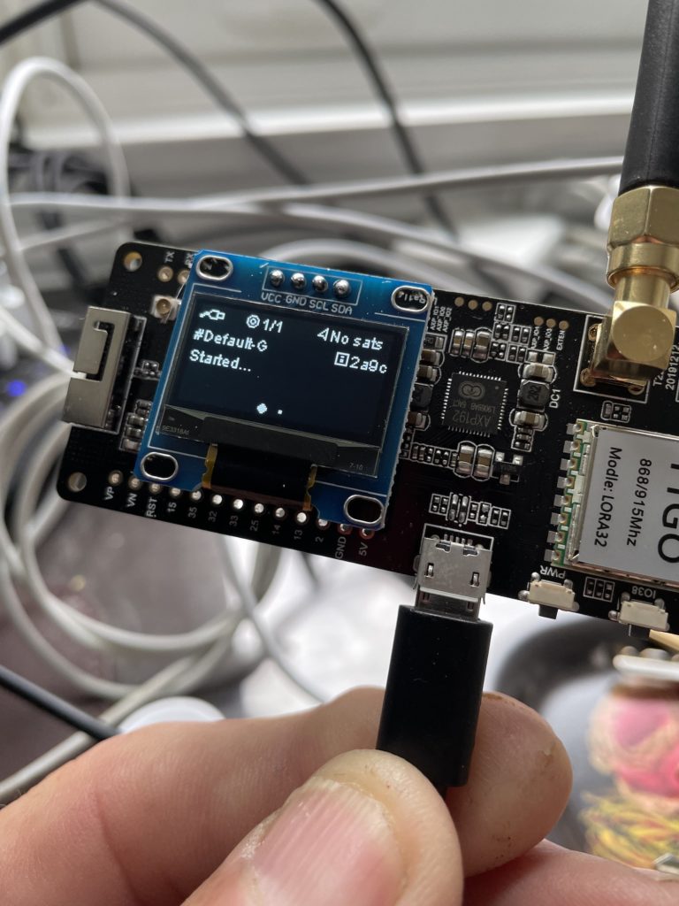
The T-Beam device has proven problematic for some folks who had sections power down and not come back. the later version use an AXP202X power control chip that manages power to all the deivces on the board. the default is for everything to be turned on, but that can easily glitch unless it’s explicily set when the code runs.
From the web:
AXP202 comprises an adaptive USB-Compatible PWM charger, 2 BUCK DC-DC converters, 5 LDOs, m
AXP202 is designed to be a highly-integrated power system management IC that is optimized for applications requiring single-cell Li-battery (Li- Ion/Polymer) and multiple output DC-DC converters. It is offering an easy-to-use and flexible complete solution which can fully meet the increasingly complexity of accurate power control required by modern application processor system.
AXP202 comprises an adaptive USB-Compatible PWM charger, 2 BUCK DC-DC converters, 5 LDOs, multiple 12-bit ADCs of voltage, current and temperature as well as 4 configurable GPIOs. To guarantee the safty and stability of power system, AXP202 has integrated various protection circuits such as Over voltage Protection(OVP)/Under voltage Protection(UVP) ,Over temperature protection(OTP),Over current protection(OCP).
With Intelligent Power Select, IPS™ circuits, AXP202 can distribute power safely and transparently among external AC-adapter, Li-battery and loaded application system, and it can still work normally when there is no battery (deeply discharged/infective battery) but only external input power source.
The AXP202 provides a small, simple solution for obtaining power from three different power sources, single-cell Li-Ion battery, USB port, and AC-adapter, and it can support rechargable backup battery too. To ensure compatibility with a wide range of system processors,
AXP202 uses a Two Wire Serial Interface (TWSI),through which application processor is capable of enabling/disabling power rails, programming voltage, visiting internal registers as well as measurement data (including Fuel Gauge). With the power monitoring results of high precision (1%, determined by the 1% BIAS resistance), end users will be always posted with the real-time power consumption, which can bring them an unprecedented experiences of power management.
Elsewhere:
I had the same problem out of the box! The 3.3V pin header read 1.8V and nothing else was powered at all. The reason is that it has an AXP192 power controller to allow the ESP to switch peripherals on & off. Have a look at the AXP202X Library by Lewis He:
https://platformio.org/lib/show/6657/AXP202X_Library
Add the following to your sketch:
#include <axp20x.h> AXP20X_Class axp;
And in Setup():
`
//Turn everything on
axp.setPowerOutPut(AXP192_LDO2, AXP202_ON);
axp.setPowerOutPut(AXP192_LDO3, AXP202_ON);
axp.setPowerOutPut(AXP192_DCDC1, AXP202_ON);
axp.setPowerOutPut(AXP192_DCDC2, AXP202_ON);
axp.setPowerOutPut(AXP192_DCDC3, AXP202_ON);
axp.setPowerOutPut(AXP192_EXTEN, AXP202_ON);
axp.setDCDC1Voltage(3300); //Set Pin header 3.3V line to 3.3V. Processor is happy down to 1.8V which saves power
//I don’t think this board has a built in LED, other than the Charge LED, controlled by this:
// AXP20X_LED_OFF,
// AXP20X_LED_BLINK_1HZ,
// AXP20X_LED_BLINK_4HZ,
// AXP20X_LED_LOW_LEVEL,
axp.setChgLEDMode(AXP20X_LED_OFF);
`
Everything will come back to life!
It turns out the ESP will opperate down to about 1.8V quite happily.
It has a load of potentially useful (cool) features including setting the voltage supplied to any of the peripherals (to save power) and measuring the current supplied to them. You can detect whether the battery is being charged – and read the charge / discharge current.
People have commented that the battery doesn’t cut-off when over-discharged. I suspect this needs explicitly setting up on this chip too.
I don’t think the last bit as necessarily correct, though the cutoff voltages might be editable. The firmware should set the charging parameters for the specified LiPo battery chemistry. But IMBW.
There are two GitHub topics
https://github.com/LilyGO/TTGO-T-Beam which seems to be an older location
and
https://github.com/Xinyuan-LilyGO/LilyGO-T-Beam which looks newer. I had a lot more luck running examoples on the second link but the first link has some examples that are more specific to particular functions and “peripherals” to the ESP32
GitHub Examples
The following example and its accompanying components appear to be the factory demo that comes loaded on the boards. I note there is nothing to explicitly turn on all the relevant peripherals. I’ll pretty up all this code do explanations of each segment.
TBeamAllFunction.ino
/*
* Test all functions of the hardware, only applicable to T-Beam, does not support other LoRa versions
* Written on November 07, 2020 Created by Lewis he
* */
#include <WiFi.h>
#include <AceButton.h>
#include <SSD1306.h>
// Library for the OLED display
#include <OLEDDisplayUi.h>
#include <RadioLib.h>
#include <TinyGPS++.h>
#include “boards.h”
using namespace ace_button;
/*
Replace the model according to the actual situation
RADIO_TYPE option:
– SX1278
– SX1276
– SX1262
*/
#define RADIO_TYPE SX1276
//If you want to use SX1262, cancel this comment
// #define RADIO_USING_SX1262
SSD1306 *oled = nullptr;
OLEDDisplayUi *ui = nullptr;
AceButton btn(BUTTON_PIN);
TinyGPSPlus gps;
String recv = “”;
// flag to indicate that a packet was received
bool receivedFlag = false;
// disable interrupt when it’s not needed
bool enableInterrupt = true;
char buff[5][256];
uint32_t gpsLoopMillis = 0;
uint32_t loraLoopMillis = 0;
uint32_t positioningMillis = 0;
uint8_t funcSelectIndex = 0;
#ifdef RADIO_USING_SX1262
RADIO_TYPE radio = new Module(RADIO_CS_PIN, RADIO_DIO1_PIN, RADIO_RST_PIN, RADIO_BUSY_PIN);
#else
RADIO_TYPE radio = new Module(RADIO_CS_PIN, RADIO_DI0_PIN, RADIO_RST_PIN, RADIO_BUSY_PIN);
#endif
void ButtonHandleEvent(AceButton *, uint8_t eventType, uint8_t buttonState);
void MsOverlay(OLEDDisplay *display, OLEDDisplayUiState *state);
void DrawFrame1(OLEDDisplay *display, OLEDDisplayUiState *state, int16_t x, int16_t y);
void DrawFrame2(OLEDDisplay *display, OLEDDisplayUiState *state, int16_t x, int16_t y);
void DrawFrame3(OLEDDisplay *display, OLEDDisplayUiState *state, int16_t x, int16_t y);
void DrawFrame4(OLEDDisplay *display, OLEDDisplayUiState *state, int16_t x, int16_t y);
void SenderLoop(void);
void GpsLoop(void);
void ReceiveLoop(void);
typedef void (*funcCallBackTypedef)(void);
funcCallBackTypedef LilyGoCallBack[] = {GpsLoop, SenderLoop, ReceiveLoop, NULL};
FrameCallback frames[] = {DrawFrame1, DrawFrame2, DrawFrame3, DrawFrame4};
OverlayCallback overlays[] = { MsOverlay };
// this function is called when a complete packet
// is received by the module
// IMPORTANT: this function MUST be ‘void’ type
// and MUST NOT have any arguments!
void setFlag(void)
{
// check if the interrupt is enabled
if (!enableInterrupt) {
return;
}
// we got a packet, set the flag
receivedFlag = true;
}
void setup()
{
initBoard();
pinMode(BUTTON_PIN, INPUT_PULLUP);
ButtonConfig *buttonConfig = btn.getButtonConfig();
buttonConfig->setEventHandler(ButtonHandleEvent);
buttonConfig->setFeature(ButtonConfig::kFeatureClick);
buttonConfig->setFeature(ButtonConfig::kFeatureLongPress);
Wire.beginTransmission(0x3C);
if (!Wire.endTransmission()) {
Serial.println(“Started OLED”);
oled = new SSD1306(0x3C, I2C_SDA, I2C_SCL);
ui = new OLEDDisplayUi(oled);
oled->init();
oled->flipScreenVertically();
oled->setFont(ArialMT_Plain_16);
oled->setTextAlignment(TEXT_ALIGN_CENTER);
ui->setTargetFPS(30);
ui->disableAutoTransition();
ui->setIndicatorPosition(BOTTOM);
ui->setIndicatorDirection(LEFT_RIGHT);
ui->setFrameAnimation(SLIDE_LEFT);
ui->setFrames(frames, sizeof(frames) / sizeof(*frames));
ui->setOverlays(overlays, sizeof(overlays) / sizeof(*overlays));
}
Serial.print(F(“[Radio] Initializing … “));
#ifndef LoRa_frequency
int state = radio.begin(868.0);
#else
int state = radio.begin(LoRa_frequency);
#endif
if (state == ERR_NONE) {
Serial.println(F(“success!”));
} else {
Serial.print(F(“failed, code “));
Serial.println(state);
while (true);
}
// set the function that will be called
// when new packet is received
#ifdef RADIO_USING_SX1262
radio.setDio1Action(setFlag);
#else
radio.setDio0Action(setFlag);
#endif
}
void loop()
{
btn.check();
if (LilyGoCallBack[funcSelectIndex]) {
LilyGoCallBack[funcSelectIndex]();
}
if (ui) {
ui->update();
}
}
void GpsLoop(void)
{
while (Serial1.available()) {
int r = Serial1.read();
Serial.write(r);
gps.encode(r);
}
if (millis() > 5000 && gps.charsProcessed() < 10) {
snprintf(buff[0], sizeof(buff[0]), “T-Beam GPS”);
snprintf(buff[1], sizeof(buff[1]), “No GPS detected”);
Serial.println(“No GPS detected”);
return;
}
if (!gps.location.isValid()) {
if (millis() – gpsLoopMillis > 1000) {
snprintf(buff[0], sizeof(buff[0]), “T-Beam GPS”);
snprintf(buff[1], sizeof(buff[1]), “Positioning(%u)S”, positioningMillis++);
gpsLoopMillis = millis();
}
} else {
if (millis() – gpsLoopMillis > 1000) {
snprintf(buff[0], sizeof(buff[0]), “UTC:%d:%d:%d”, gps.time.hour(), gps.time.minute(), gps.time.second());
snprintf(buff[1], sizeof(buff[1]), “LNG:%.4f”, gps.location.lng());
snprintf(buff[2], sizeof(buff[2]), “LAT:%.4f”, gps.location.lat());
snprintf(buff[3], sizeof(buff[3]), “satellites:%u”, gps.satellites.value());
Serial.printf(“UTC:%d:%d:%d-LNG:%.4f-LAT:%.4f-satellites:%u\n”,
gps.time.hour(),
gps.time.minute(),
gps.time.second(),
gps.location.lng(),
gps.location.lat(),
gps.satellites.value());
gpsLoopMillis = millis();
}
}
}
void SenderLoop(void)
{
snprintf(buff[0], sizeof(buff[0]), “T-Beam Lora Sender”);
// Send data every 3 seconds
if (millis() – loraLoopMillis > 3000) {
int transmissionState = ERR_NONE;
transmissionState = radio.startTransmit(String(loraLoopMillis).c_str());
// check if the previous transmission finished
if (receivedFlag) {
// disable the interrupt service routine while
// processing the data
enableInterrupt = false;
// reset flag
receivedFlag = false;
if (transmissionState == ERR_NONE) {
// packet was successfully sent
Serial.println(F(“transmission finished!”));
// NOTE: when using interrupt-driven transmit method,
// it is not possible to automatically measure
// transmission data rate using getDataRate()
} else {
Serial.print(F(“failed, code “));
Serial.println(transmissionState);
}
// wait a second before transmitting again
// delay(1000);
// send another one
Serial.print(F(“[RADIO] Sending another packet … “));
// you can transmit C-string or Arduino string up to
// 256 characters long
transmissionState = radio.startTransmit(String(loraLoopMillis).c_str());
// you can also transmit byte array up to 256 bytes long
/*
byte byteArr[] = {0x01, 0x23, 0x45, 0x67,
0x89, 0xAB, 0xCD, 0xEF};
int state = radio.startTransmit(byteArr, 8);
*/
// we’re ready to send more packets,
// enable interrupt service routine
enableInterrupt = true;
}
snprintf(buff[1], sizeof(buff[1]), “Send: %u”, loraLoopMillis);
loraLoopMillis = millis();
Serial.println(buff[1]);
}
}
void ReceiveLoop(void)
{
snprintf(buff[0], sizeof(buff[0]), “T-Beam Lora Received”);
// check if the flag is set
if (receivedFlag) {
// disable the interrupt service routine while
// processing the data
enableInterrupt = false;
// reset flag
receivedFlag = false;
// you can read received data as an Arduino String
int state = radio.readData(recv);
// you can also read received data as byte array
/*
byte byteArr[8];
int state = radio.readData(byteArr, 8);
*/
if (state == ERR_NONE) {
// packet was successfully received
Serial.println(F(“[RADIO] Received packet!”));
// print data of the packet
Serial.print(F(“[RADIO] Data:\t\t”));
Serial.println(recv);
// print RSSI (Received Signal Strength Indicator)
Serial.print(F(“[RADIO] RSSI:\t\t”));
Serial.print(radio.getRSSI());
Serial.println(F(” dBm”));
snprintf(buff[1], sizeof(buff[1]), “RSSI:%.2f dBm”, radio.getRSSI());
// print SNR (Signal-to-Noise Ratio)
Serial.print(F(“[RADIO] SNR:\t\t”));
Serial.print(radio.getSNR());
Serial.println(F(” dB”));
} else if (state == ERR_CRC_MISMATCH) {
// packet was received, but is malformed
Serial.println(F(“CRC error!”));
} else {
// some other error occurred
Serial.print(F(“failed, code “));
Serial.println(state);
}
// put module back to listen mode
radio.startReceive();
// we’re ready to receive more packets,
// enable interrupt service routine
enableInterrupt = true;
}
}
/************************************
* BUTTON
* *********************************/
void ButtonHandleEvent(AceButton *, uint8_t eventType, uint8_t buttonState)
{
switch (eventType) {
case AceButton::kEventClicked:
if (ui) {
ui->nextFrame();
}
funcSelectIndex++;
funcSelectIndex %= sizeof(LilyGoCallBack) / sizeof(*LilyGoCallBack);
if (funcSelectIndex == 2) {
Serial.print(F(“[RADIO] Starting to listen … “));
int state = radio.startReceive();
if (state == ERR_NONE) {
Serial.println(F(“success!”));
} else {
Serial.print(F(“failed, code “));
Serial.println(state);
}
memset(buff, 0, sizeof(buff));
}
break;
case AceButton::kEventLongPressed:
//Power off all peripherals
disablePeripherals();
//If the power is not turned off, the peripheral should be set to sleep
/*
radio.sleep();
if (oled) {
oled->displayOff();
}
*/
delay(1000);
esp_sleep_enable_ext1_wakeup(BUTTON_PIN_MASK, ESP_EXT1_WAKEUP_ALL_LOW);
esp_deep_sleep_start();
break;
}
}
/************************************
* DISPLAY
* *********************************/
void MsOverlay(OLEDDisplay *display, OLEDDisplayUiState *state)
{
static char volbuffer[128];
display->setTextAlignment(TEXT_ALIGN_LEFT);
display->setFont(ArialMT_Plain_10);
display->drawString(0, 0, “LilyGo”);
multi_heap_info_t info;
heap_caps_get_info(&info, MALLOC_CAP_INTERNAL);
snprintf(volbuffer, sizeof(volbuffer), “%u/%uKB”, info.total_allocated_bytes / 1024, info.total_free_bytes / 1024);
display->drawString(75, 0, volbuffer);
}
void DrawFrame1(OLEDDisplay *display, OLEDDisplayUiState *state, int16_t x, int16_t y)
{
display->setFont(ArialMT_Plain_10);
display->setTextAlignment(TEXT_ALIGN_CENTER);
if (!gps.location.isValid()) {
display->drawString(64 + x, 11 + y, buff[0]);
display->drawString(64 + x, 22 + y, buff[1]);
} else {
display->drawString(64 + x, 11 + y, buff[0]);
display->drawString(64 + x, 22 + y, buff[1]);
display->drawString(64 + x, 33 + y, buff[2]);
display->drawString(64 + x, 44 + y, buff[3]);
}
}
void DrawFrame2(OLEDDisplay *display, OLEDDisplayUiState *state, int16_t x, int16_t y)
{
display->setFont(ArialMT_Plain_10);
display->setTextAlignment(TEXT_ALIGN_CENTER);
display->drawString(64 + x, 11 + y, buff[0]);
display->drawString(64 + x, 22 + y, buff[1]);
}
void DrawFrame3(OLEDDisplay *display, OLEDDisplayUiState *state, int16_t x, int16_t y)
{
display->setFont(ArialMT_Plain_10);
display->setTextAlignment(TEXT_ALIGN_CENTER);
display->drawString(64 + x, 9 + y, buff[0]);
display->drawString(64 + x, 22 + y, recv == “” ? “No message” : recv);
display->drawString(64 + x, 35 + y, buff[1]);
}
void DrawFrame4(OLEDDisplay *display, OLEDDisplayUiState *state, int16_t x, int16_t y)
{
bool batteryConnect = PMU.isBatteryConnect();
snprintf(buff[0], sizeof(buff[0]), “BATTERY:%s”, batteryConnect ? “CONNECT” : “DISCONNECT”);
if (batteryConnect) {
snprintf(buff[1], sizeof(buff[1]), “VOLTAGE:%.2f”, PMU.getBattVoltage());
snprintf(buff[2], sizeof(buff[2]), “CURRENT:%.2f”, PMU.getBattDischargeCurrent());
} else {
snprintf(buff[1], sizeof(buff[1]), “VOLTAGE:%.2f”, PMU.getVbusVoltage());
snprintf(buff[2], sizeof(buff[2]), “CURRENT:%.2f”, PMU.getVbusCurrent());
}
display->setFont(ArialMT_Plain_10);
display->setTextAlignment(TEXT_ALIGN_CENTER);
display->drawString(64 + x, 12 + y, buff[0]);
display->drawString(64 + x, 24 + y, buff[1]);
display->drawString(64 + x, 37 + y, buff[2]);
}
Board.h
/*
* Test all functions of the hardware, only applicable to T-Beam, does not support other LoRa versions
* Written on November 07, 2020 Created by Lewis he
* */
#include <WiFi.h>
#include <AceButton.h>
#include <SSD1306.h>
#include <OLEDDisplayUi.h>
#include <RadioLib.h>
#include <TinyGPS++.h>
#include “boards.h”
using namespace ace_button;
/*
Replace the model according to the actual situation
RADIO_TYPE option:
– SX1278
– SX1276
– SX1262
*/
#define RADIO_TYPE SX1276
//If you want to use SX1262, cancel this comment
// #define RADIO_USING_SX1262
SSD1306 *oled = nullptr;
OLEDDisplayUi *ui = nullptr;
AceButton btn(BUTTON_PIN);
TinyGPSPlus gps;
String recv = “”;
// flag to indicate that a packet was received
bool receivedFlag = false;
// disable interrupt when it’s not needed
bool enableInterrupt = true;
char buff[5][256];
uint32_t gpsLoopMillis = 0;
uint32_t loraLoopMillis = 0;
uint32_t positioningMillis = 0;
uint8_t funcSelectIndex = 0;
#ifdef RADIO_USING_SX1262
RADIO_TYPE radio = new Module(RADIO_CS_PIN, RADIO_DIO1_PIN, RADIO_RST_PIN, RADIO_BUSY_PIN);
#else
RADIO_TYPE radio = new Module(RADIO_CS_PIN, RADIO_DI0_PIN, RADIO_RST_PIN, RADIO_BUSY_PIN);
#endif
void ButtonHandleEvent(AceButton *, uint8_t eventType, uint8_t buttonState);
void MsOverlay(OLEDDisplay *display, OLEDDisplayUiState *state);
void DrawFrame1(OLEDDisplay *display, OLEDDisplayUiState *state, int16_t x, int16_t y);
void DrawFrame2(OLEDDisplay *display, OLEDDisplayUiState *state, int16_t x, int16_t y);
void DrawFrame3(OLEDDisplay *display, OLEDDisplayUiState *state, int16_t x, int16_t y);
void DrawFrame4(OLEDDisplay *display, OLEDDisplayUiState *state, int16_t x, int16_t y);
void SenderLoop(void);
void GpsLoop(void);
void ReceiveLoop(void);
typedef void (*funcCallBackTypedef)(void);
funcCallBackTypedef LilyGoCallBack[] = {GpsLoop, SenderLoop, ReceiveLoop, NULL};
FrameCallback frames[] = {DrawFrame1, DrawFrame2, DrawFrame3, DrawFrame4};
OverlayCallback overlays[] = { MsOverlay };
// this function is called when a complete packet
// is received by the module
// IMPORTANT: this function MUST be ‘void’ type
// and MUST NOT have any arguments!
void setFlag(void)
{
// check if the interrupt is enabled
if (!enableInterrupt) {
return;
}
// we got a packet, set the flag
receivedFlag = true;
}
void setup()
{
initBoard();
pinMode(BUTTON_PIN, INPUT_PULLUP);
ButtonConfig *buttonConfig = btn.getButtonConfig();
buttonConfig->setEventHandler(ButtonHandleEvent);
buttonConfig->setFeature(ButtonConfig::kFeatureClick);
buttonConfig->setFeature(ButtonConfig::kFeatureLongPress);
Wire.beginTransmission(0x3C);
if (!Wire.endTransmission()) {
Serial.println(“Started OLED”);
oled = new SSD1306(0x3C, I2C_SDA, I2C_SCL);
ui = new OLEDDisplayUi(oled);
oled->init();
oled->flipScreenVertically();
oled->setFont(ArialMT_Plain_16);
oled->setTextAlignment(TEXT_ALIGN_CENTER);
ui->setTargetFPS(30);
ui->disableAutoTransition();
ui->setIndicatorPosition(BOTTOM);
ui->setIndicatorDirection(LEFT_RIGHT);
ui->setFrameAnimation(SLIDE_LEFT);
ui->setFrames(frames, sizeof(frames) / sizeof(*frames));
ui->setOverlays(overlays, sizeof(overlays) / sizeof(*overlays));
}
Serial.print(F(“[Radio] Initializing … “));
#ifndef LoRa_frequency
int state = radio.begin(868.0);
#else
int state = radio.begin(LoRa_frequency);
#endif
if (state == ERR_NONE) {
Serial.println(F(“success!”));
} else {
Serial.print(F(“failed, code “));
Serial.println(state);
while (true);
}
// set the function that will be called
// when new packet is received
#ifdef RADIO_USING_SX1262
radio.setDio1Action(setFlag);
#else
radio.setDio0Action(setFlag);
#endif
}
void loop()
{
btn.check();
if (LilyGoCallBack[funcSelectIndex]) {
LilyGoCallBack[funcSelectIndex]();
}
if (ui) {
ui->update();
}
}
void GpsLoop(void)
{
while (Serial1.available()) {
int r = Serial1.read();
Serial.write(r);
gps.encode(r);
}
if (millis() > 5000 && gps.charsProcessed() < 10) {
snprintf(buff[0], sizeof(buff[0]), “T-Beam GPS”);
snprintf(buff[1], sizeof(buff[1]), “No GPS detected”);
Serial.println(“No GPS detected”);
return;
}
if (!gps.location.isValid()) {
if (millis() – gpsLoopMillis > 1000) {
snprintf(buff[0], sizeof(buff[0]), “T-Beam GPS”);
snprintf(buff[1], sizeof(buff[1]), “Positioning(%u)S”, positioningMillis++);
gpsLoopMillis = millis();
}
} else {
if (millis() – gpsLoopMillis > 1000) {
snprintf(buff[0], sizeof(buff[0]), “UTC:%d:%d:%d”, gps.time.hour(), gps.time.minute(), gps.time.second());
snprintf(buff[1], sizeof(buff[1]), “LNG:%.4f”, gps.location.lng());
snprintf(buff[2], sizeof(buff[2]), “LAT:%.4f”, gps.location.lat());
snprintf(buff[3], sizeof(buff[3]), “satellites:%u”, gps.satellites.value());
Serial.printf(“UTC:%d:%d:%d-LNG:%.4f-LAT:%.4f-satellites:%u\n”,
gps.time.hour(),
gps.time.minute(),
gps.time.second(),
gps.location.lng(),
gps.location.lat(),
gps.satellites.value());
gpsLoopMillis = millis();
}
}
}
void SenderLoop(void)
{
snprintf(buff[0], sizeof(buff[0]), “T-Beam Lora Sender”);
// Send data every 3 seconds
if (millis() – loraLoopMillis > 3000) {
int transmissionState = ERR_NONE;
transmissionState = radio.startTransmit(String(loraLoopMillis).c_str());
// check if the previous transmission finished
if (receivedFlag) {
// disable the interrupt service routine while
// processing the data
enableInterrupt = false;
// reset flag
receivedFlag = false;
if (transmissionState == ERR_NONE) {
// packet was successfully sent
Serial.println(F(“transmission finished!”));
// NOTE: when using interrupt-driven transmit method,
// it is not possible to automatically measure
// transmission data rate using getDataRate()
} else {
Serial.print(F(“failed, code “));
Serial.println(transmissionState);
}
// wait a second before transmitting again
// delay(1000);
// send another one
Serial.print(F(“[RADIO] Sending another packet … “));
// you can transmit C-string or Arduino string up to
// 256 characters long
transmissionState = radio.startTransmit(String(loraLoopMillis).c_str());
// you can also transmit byte array up to 256 bytes long
/*
byte byteArr[] = {0x01, 0x23, 0x45, 0x67,
0x89, 0xAB, 0xCD, 0xEF};
int state = radio.startTransmit(byteArr, 8);
*/
// we’re ready to send more packets,
// enable interrupt service routine
enableInterrupt = true;
}
snprintf(buff[1], sizeof(buff[1]), “Send: %u”, loraLoopMillis);
loraLoopMillis = millis();
Serial.println(buff[1]);
}
}
void ReceiveLoop(void)
{
snprintf(buff[0], sizeof(buff[0]), “T-Beam Lora Received”);
// check if the flag is set
if (receivedFlag) {
// disable the interrupt service routine while
// processing the data
enableInterrupt = false;
// reset flag
receivedFlag = false;
// you can read received data as an Arduino String
int state = radio.readData(recv);
// you can also read received data as byte array
/*
byte byteArr[8];
int state = radio.readData(byteArr, 8);
*/
if (state == ERR_NONE) {
// packet was successfully received
Serial.println(F(“[RADIO] Received packet!”));
// print data of the packet
Serial.print(F(“[RADIO] Data:\t\t”));
Serial.println(recv);
// print RSSI (Received Signal Strength Indicator)
Serial.print(F(“[RADIO] RSSI:\t\t”));
Serial.print(radio.getRSSI());
Serial.println(F(” dBm”));
snprintf(buff[1], sizeof(buff[1]), “RSSI:%.2f dBm”, radio.getRSSI());
// print SNR (Signal-to-Noise Ratio)
Serial.print(F(“[RADIO] SNR:\t\t”));
Serial.print(radio.getSNR());
Serial.println(F(” dB”));
} else if (state == ERR_CRC_MISMATCH) {
// packet was received, but is malformed
Serial.println(F(“CRC error!”));
} else {
// some other error occurred
Serial.print(F(“failed, code “));
Serial.println(state);
}
// put module back to listen mode
radio.startReceive();
// we’re ready to receive more packets,
// enable interrupt service routine
enableInterrupt = true;
}
}
/************************************
* BUTTON
* *********************************/
void ButtonHandleEvent(AceButton *, uint8_t eventType, uint8_t buttonState)
{
switch (eventType) {
case AceButton::kEventClicked:
if (ui) {
ui->nextFrame();
}
funcSelectIndex++;
funcSelectIndex %= sizeof(LilyGoCallBack) / sizeof(*LilyGoCallBack);
if (funcSelectIndex == 2) {
Serial.print(F(“[RADIO] Starting to listen … “));
int state = radio.startReceive();
if (state == ERR_NONE) {
Serial.println(F(“success!”));
} else {
Serial.print(F(“failed, code “));
Serial.println(state);
}
memset(buff, 0, sizeof(buff));
}
break;
case AceButton::kEventLongPressed:
//Power off all peripherals
disablePeripherals();
//If the power is not turned off, the peripheral should be set to sleep
/*
radio.sleep();
if (oled) {
oled->displayOff();
}
*/
delay(1000);
esp_sleep_enable_ext1_wakeup(BUTTON_PIN_MASK, ESP_EXT1_WAKEUP_ALL_LOW);
esp_deep_sleep_start();
break;
}
}
/************************************
* DISPLAY
* *********************************/
void MsOverlay(OLEDDisplay *display, OLEDDisplayUiState *state)
{
static char volbuffer[128];
display->setTextAlignment(TEXT_ALIGN_LEFT);
display->setFont(ArialMT_Plain_10);
display->drawString(0, 0, “LilyGo”);
multi_heap_info_t info;
heap_caps_get_info(&info, MALLOC_CAP_INTERNAL);
snprintf(volbuffer, sizeof(volbuffer), “%u/%uKB”, info.total_allocated_bytes / 1024, info.total_free_bytes / 1024);
display->drawString(75, 0, volbuffer);
}
void DrawFrame1(OLEDDisplay *display, OLEDDisplayUiState *state, int16_t x, int16_t y)
{
display->setFont(ArialMT_Plain_10);
display->setTextAlignment(TEXT_ALIGN_CENTER);
if (!gps.location.isValid()) {
display->drawString(64 + x, 11 + y, buff[0]);
display->drawString(64 + x, 22 + y, buff[1]);
} else {
display->drawString(64 + x, 11 + y, buff[0]);
display->drawString(64 + x, 22 + y, buff[1]);
display->drawString(64 + x, 33 + y, buff[2]);
display->drawString(64 + x, 44 + y, buff[3]);
}
}
void DrawFrame2(OLEDDisplay *display, OLEDDisplayUiState *state, int16_t x, int16_t y)
{
display->setFont(ArialMT_Plain_10);
display->setTextAlignment(TEXT_ALIGN_CENTER);
display->drawString(64 + x, 11 + y, buff[0]);
display->drawString(64 + x, 22 + y, buff[1]);
}
void DrawFrame3(OLEDDisplay *display, OLEDDisplayUiState *state, int16_t x, int16_t y)
{
display->setFont(ArialMT_Plain_10);
display->setTextAlignment(TEXT_ALIGN_CENTER);
display->drawString(64 + x, 9 + y, buff[0]);
display->drawString(64 + x, 22 + y, recv == “” ? “No message” : recv);
display->drawString(64 + x, 35 + y, buff[1]);
}
void DrawFrame4(OLEDDisplay *display, OLEDDisplayUiState *state, int16_t x, int16_t y)
{
bool batteryConnect = PMU.isBatteryConnect();
snprintf(buff[0], sizeof(buff[0]), “BATTERY:%s”, batteryConnect ? “CONNECT” : “DISCONNECT”);
if (batteryConnect) {
snprintf(buff[1], sizeof(buff[1]), “VOLTAGE:%.2f”, PMU.getBattVoltage());
snprintf(buff[2], sizeof(buff[2]), “CURRENT:%.2f”, PMU.getBattDischargeCurrent());
} else {
snprintf(buff[1], sizeof(buff[1]), “VOLTAGE:%.2f”, PMU.getVbusVoltage());
snprintf(buff[2], sizeof(buff[2]), “CURRENT:%.2f”, PMU.getVbusCurrent());
}
display->setFont(ArialMT_Plain_10);
display->setTextAlignment(TEXT_ALIGN_CENTER);
display->drawString(64 + x, 12 + y, buff[0]);
display->drawString(64 + x, 24 + y, buff[1]);
display->drawString(64 + x, 37 + y, buff[2]);
}
Utilities.h
#pragma once
/*
* This sample program only supports T-Beam
* */
// #define LILYGO_TBeam_V0_7
// #define LILYGO_TBeam_V1_0
#define LILYGO_TBeam_V1_1
/*
* The default program uses 868MHz,
* if you need to change it,
* please open this note and change to the frequency you need to test
* */
// #define LoRa_frequency 433.0
#define UNUSE_PIN (0)
#if defined(LILYGO_TBeam_V0_7)
#define GPS_RX_PIN 12
#define GPS_TX_PIN 15
#define BUTTON_PIN 39
#define BUTTON_PIN_MASK GPIO_SEL_39
#define I2C_SDA 21
#define I2C_SCL 22
#define RADIO_SCLK_PIN 5
#define RADIO_MISO_PIN 19
#define RADIO_MOSI_PIN 27
#define RADIO_CS_PIN 18
#define RADIO_DI0_PIN 26
#define RADIO_RST_PIN 23
#define RADIO_DIO1_PIN 33
#define RADIO_BUSY_PIN 32
#define BOARD_LED 14
#define LED_ON HIGH
#define LED_OFF LOW
#define GPS_BAUD_RATE 9600
#define HAS_GPS
#define HAS_DISPLAY //Optional, bring your own board, no OLED !!
#elif defined(LILYGO_TBeam_V1_0) || defined(LILYGO_TBeam_V1_1)
#define GPS_RX_PIN 34
#define GPS_TX_PIN 12
#define BUTTON_PIN 38
#define BUTTON_PIN_MASK GPIO_SEL_38
#define I2C_SDA 21
#define I2C_SCL 22
#define PMU_IRQ 35
#define RADIO_SCLK_PIN 5
#define RADIO_MISO_PIN 19
#define RADIO_MOSI_PIN 27
#define RADIO_CS_PIN 18
#define RADIO_DI0_PIN 26
#define RADIO_RST_PIN 23
#define RADIO_DIO1_PIN 33
#define RADIO_BUSY_PIN 32
#define BOARD_LED 4
#define LED_ON LOW
#define LED_OFF HIGH
#define GPS_BAUD_RATE 9600
#define HAS_GPS
#define HAS_DISPLAY //Optional, bring your own board, no OLED !!
#elif defined(LILYGO_T3_V1_0)
#define I2C_SDA 4
#define I2C_SCL 15
#define OLED_RST 16
#define RADIO_SCLK_PIN 5
#define RADIO_MISO_PIN 19
#define RADIO_MOSI_PIN 27
#define RADIO_CS_PIN 18
#define RADIO_DI0_PIN 26
#define RADIO_RST_PIN 14
#define RADIO_DIO1_PIN 33
#define RADIO_BUSY_PIN 32
#define HAS_DISPLAY
#elif defined(LILYGO_T3_V1_6)
#define I2C_SDA 21
#define I2C_SCL 22
#define OLED_RST UNUSE_PIN
#define RADIO_SCLK_PIN 5
#define RADIO_MISO_PIN 19
#define RADIO_MOSI_PIN 27
#define RADIO_CS_PIN 18
#define RADIO_DI0_PIN 26
#define RADIO_RST_PIN 23
#define RADIO_DIO1_PIN 33
#define RADIO_BUSY_PIN 32
#define SDCARD_MOSI 15
#define SDCARD_MISO 2
#define SDCARD_SCLK 14
#define SDCARD_CS 13
#define BOARD_LED 25
#define LED_ON HIGH
#define ADC_PIN 35
#define HAS_SDCARD
#define HAS_DISPLAY
#elif defined(LILYGO_T3_V2_0)
#define I2C_SDA 21
#define I2C_SCL 22
#define OLED_RST UNUSE_PIN
#define RADIO_SCLK_PIN 5
#define RADIO_MISO_PIN 19
#define RADIO_MOSI_PIN 27
#define RADIO_CS_PIN 18
#define RADIO_DI0_PIN 26
#define RADIO_RST_PIN 14
#define RADIO_DIO1_PIN UNUSE_PIN
#define RADIO_BUSY_PIN UNUSE_PIN
#define SDCARD_MOSI 15
#define SDCARD_MISO 2
#define SDCARD_SCLK 14
#define SDCARD_CS 13
#define BOARD_LED 0
#define LED_ON LOW
#define HAS_DISPLAY
#define HAS_SDCARD
#else
#error “Please select the version you purchased in utilities.h”
#endif